How to control W5100S-EVB-Pico with Azure IoT Central Commands
In the last article, I covered how to authenticate and connect the W5100S-EVB-Pico to Azure IoT Central using an X.509 certificate.
The above process can be briefly summarized as follows.
- W5100S-EVB-Pico development environment installation
- Create and configure IoT Central application
- Generating X.509 Certificates (Using OpenSSL)
- Download and build the project
- Run and monitoring
In this article, I will summarize how to send a C2D(Cloud to Device) message to the connected W5100-EVB-Pico and use it to control another device(s).
There are several ways to use C2D messages in Azure IoT Central, and I used Commands.
Commands enable remote management, such as controlling devices or changing settings. Alternatively, state data may be collected from the device.
More details can be found in the guide document below.
Based on the W5100S-EVB-Pico device, adding Azure IoT functions for using related functions and simply controlling an external device (Raspberry Pi 3) using GPIO.
Since it is based on the previous project, it is assumed that steps 1 to 3 have been preceded.
Device preparation
The components used in this article is as follows.
- W5100S-EVB-Pico
- Raspberry Pi 3 (to be controlled, possibly other devices)
- Jumper cable
- Ethernet cable
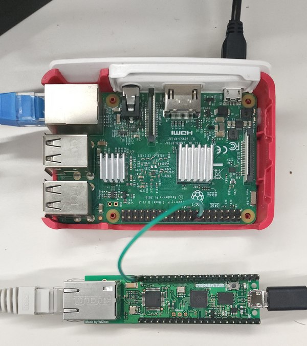
In addition to the existing hardware configuration, I needed a control target, and I had a Raspberry Pi on my desk, so I used it. If you can control the GPIO and run python, you can use any device I think.
I selected a GPIO pin and connected it to W5100S-EVB-Pico using a jumper cable.
Prepare Project
In the last article, I used the provisioning example in RP2040-HAT-AZURE-C repository of WIZNet.
If you already downloaded project, you can use it as is, otherwise, download it using git clone.
git clone https://github.com/Wiznet/RP2040-HAT-AZURE-C
Write code
main.c
Set the application to be used. I used the X.509 Provisioning sample.
// The application you wish to use should be uncommented
//
//#define APP_TELEMETRY
//#define APP_C2D
//#define APP_CLI_X509
#define APP_PROV_X509
sample_certs.c
Add the previously created certificate as a variable value.
| Variable | Certificates |
|---|---|
| pico_az_CERTIFICATE | device.crt certificate |
| pico_az_PRIVATE_KEY | device.key certificate |
| pico_az_id_scope | IoT Central ID scope |
| pico_az_COMMON_NAME | Device ID |
prov_dev_client_ll_sample.c
In the sample source code, add and register a callback function for calling IoT Central Commands.
Related examples can be found at the link below.
The process of code as follows.
- Callback function call when sending commands
- Method name comparison (Use Name: powerReset)
- Perform setting action and send response
In W5100S-EVB-Pico, I used GPIO15. (GP15)
Pinout can be referred to at the following link.
As an option, I added a user LED control temporarily to check whether the function works.
#define RESET_GPIO  15
#define LED_PIN     25
static int deviceMethodCallback(const char* method_name, const unsigned char* payload, size_t size, unsigned char** response, size_t* response_size, void* userContextCallback)
{
    (void)userContextCallback;
    (void)payload;
    (void)size;

    int result;

    // User led on
    gpio_put(LED_PIN, 1);
    printf("Device method %s arrived...\n", method_name);

    if (strcmp("powerReset", method_name) == 0) {
        printf("\nReceived device powerReset request.\n");

        const char deviceMethodResponse[] = "{ \"Response\": \"powerReset OK\" }";
        *response_size = sizeof(deviceMethodResponse)-1;
        *response = malloc(*response_size);
        (void)memcpy(*response, deviceMethodResponse, *response_size);
        sleep_ms(500);

        gpio_put(RESET_GPIO, 1);
        sleep_ms(100);
        gpio_put(RESET_GPIO, 0);

        result = 200;
    } else {
        // All other entries are ignored.
        const char deviceMethodResponse[] = "{ }";
        *response_size = sizeof(deviceMethodResponse)-1;
        *response = malloc(*response_size);
        (void)memcpy(*response, deviceMethodResponse, *response_size);
        result = -1;
    }

    // User led off
    gpio_put(LED_PIN, 0);

    return result;
}
And, register the device method callback to the existing device client handle.
(void)IoTHubDeviceClient_LL_SetMessageCallback(device_ll_handle, receive_msg_callback, &iothub_info);
// added line
(void)IoTHubDeviceClient_LL_SetDeviceMethodCallback(device_ll_handle, deviceMethodCallback, NULL);
Writing Python code for Raspberry Pi 3
A Raspberry Pi 3 will be controlled, I wrote Python code to monitor the GPIO status and perform some actions.
To write the code, you can connect to the Raspberry Pi and write it with an editor such as VIM, or you can write it on the host PC and copy the code with Samba or scp.
Here, I used VS Code with Samba, to edit and test repeatedly.
The contents are as follows.
- BCM mode used
- Selectable between Board mode and BCM mode
- Use of BCM mode based on GPIO Pin
- See Pinmap: Raspberry Pi Pinmap
- GPIO Falling event detection
- Performs the set action when an event occurs (eg. reboot)
gpio_test.py
import RPi.GPIO as gpio
import time
import os

channel = 23

gpio.setmode(gpio.BCM)

# BCM23 (pin 16)
gpio.setup(channel, gpio.IN, pull_up_down=gpio.PUD_UP)

def restart():
    print('System will be restart...')
    time.sleep(2)
    os.system("sudo reboot")

def on_falling(channel):
    print(f'gpio falling event detected! {channel}')
    restart()

try:
    # Add event detect and callback function
    gpio.add_event_detect(channel, gpio.FALLING, callback=on_falling, bouncetime=200)

    # Wait for event
    while True:
        time.sleep(1)
except KeyboardInterrupt:
    gpio.cleanup()
finally:
    gpio.cleanup()
Azure IoT Central application Setup
Modify Device Template
Add a Command component
In the existing template configuration, added a Command type capability with the name powerReset.
If you have never created a template, add a value after creating it.
The name value is the name of the method actually called from device and is case-sensitive.

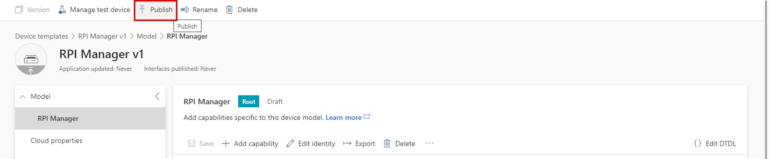
After saving, the changes are applied when publish is completed.
When publish is complete, the Publish button is disabled.
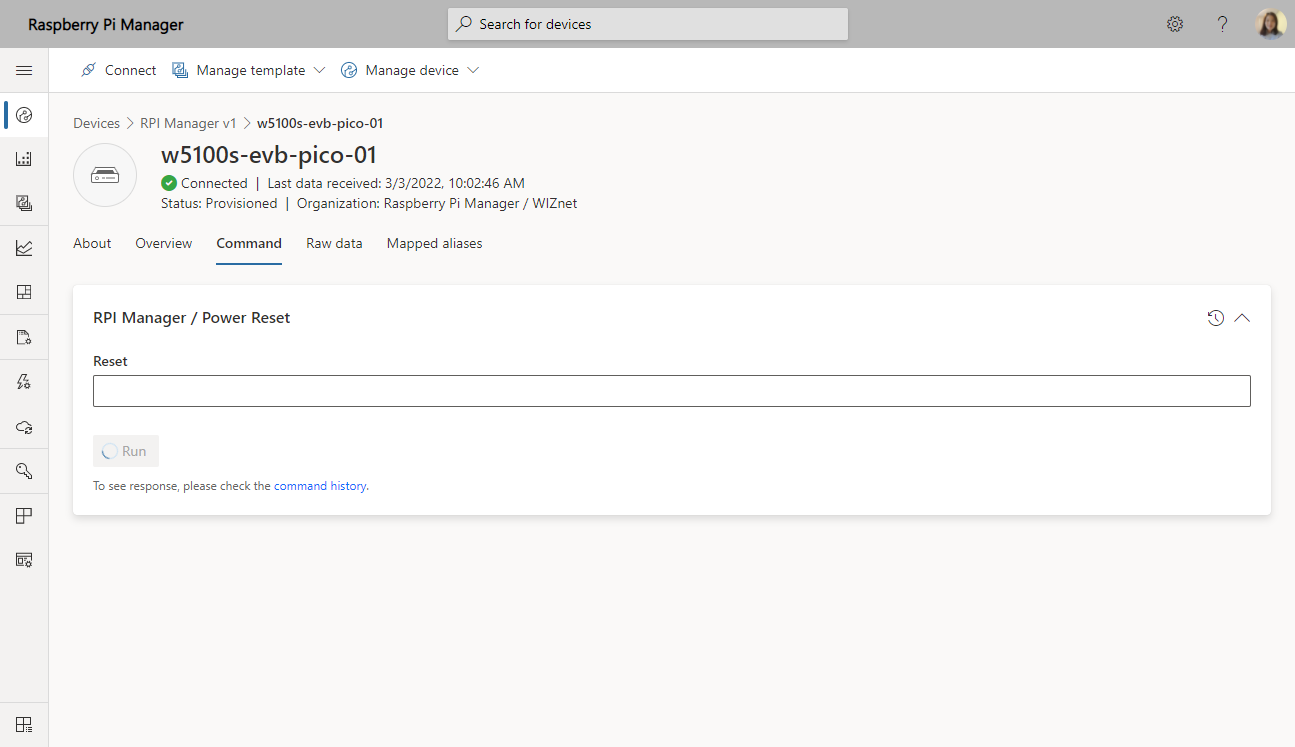
Now, once go to the device detail page, you can see the Command tab and there is a component added previously.

Commands can be sent to the device through this tab.
Build, Run and Monitor
Build and upload firmware to W5100S-EVB-Pico
Build the modified code and upload it to the device.
You can refer to the previous article on how to build and upload.
Additionally, I used Tera Term to monitor real-time.
Execute python code on Raspberry Pi 3
After connecting to Raspberry Pi 3 via ssh, run the python code.
python gpio_test.py
Send Command and Monitoring
Go to the Commands tab of the device page and click Run button of powerReset component to send the command.
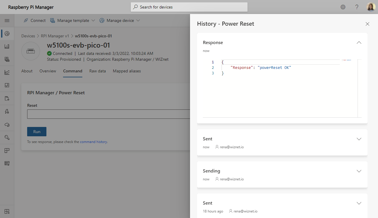
A command is sent to the connected device, and when a response is received, it is treated as a success command.
You can check command execution logs such as execution time and response through Command History.
For the device monitoring, I setup the windows as follow image.
The left terminal monitors W5100S-EVB-Pico through the COM port, and the right terminal is the screen connected to Raspberry Pi through SSH.
- Sending commands from IoT Central
- Receive powerReset command from W5100-EVB-Pico
- Send signal to RPI3 via GPIO
- RPI3 Reboot by receiving a signal from W5100S-EVB-Pico

You can see that the command is received normally and the raspberry pi reboots and the SSH connection is disconnected.
In this article, only a simple reboot operation is applied, but if you apply it, you will be able to control and manage various components.